Ventilation control

Supply and return air cascade control

Application description

The return air temperature is controlled via a supply/return air cascade.
The cascade circuit consists of a main control loop (return air temperature control system)
and an auxiliary control loop (supply air temperature control system).

Plan der Lueftungsregelung

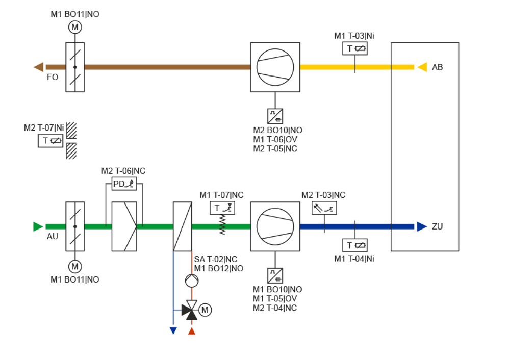
The system consists of:

  • Smart Actuator, type AKM115SAF232 (ball valve actuator for air heater)
    • Air heater pump malfunction (SA T-02|NC)
  • I/O-Modul M1, type SAIO100F020 (I/O extension)
    • Return air temperature (I/O module M1 T-03|Ni)
    • Supply air temperature (I/O module M1 T-04|Ni)
    • Supply fan FC (I/O module M1 T-05|OV)
    • Supply fan FC (I/O module M1 T-05|OV)
    • Frost protection thermostat (I/O module M1 T-07|NC)
    • Supply air fan release (I/O module M1 BO10|NO)
    • Supply/return air dampers (I/O module M1 BO11|NO)
    • Air heater pump (I/O module M1 BO12|NO)
  • I/O-Modul M2, type SAIO100F020 (I/O extension)
    • Smoke detector (I/O module M2 T-03|NC)
    • Supply fan malfunction (I/O module M2 T-04|NC)
    • Return fan malfunction (I/O module M2 T-05|NC)
    • Filter monitoring (I/O module M2 T-06|NC)
    • Filterüberwachung (I/O-Modul M2 T-06|NC)
    • Outside temperature (I/O module M2 T-07|Ni)
    • Return fan release (I/O module M2 BO10|NO)
Back